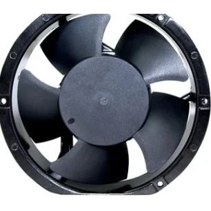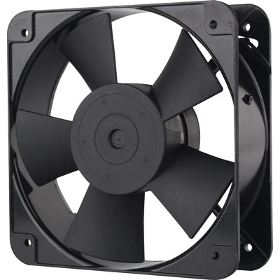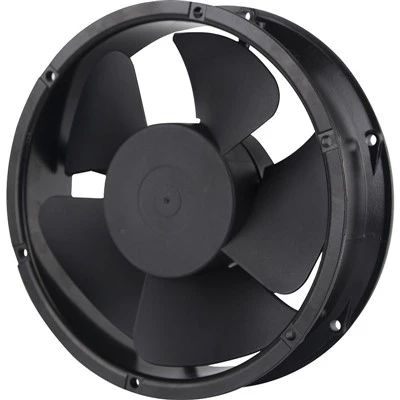
To address the contradiction between low air pressure in air conditioner fans and the need for both high airflow and low noise, this study selected a high-performance axial flow fan prototype for air conditioning as a comparative research model for swept-back design. The prototype's basic structure includes: impeller outer diameter 409 mm, impeller diameter 120 mm, impeller-to-impeller ratio 0.29, 4 blades, flow rate 2220 m³/h, static pressure 20 Pa, and rotational speed 880 r/min. The new fan design prioritizes ensuring sufficient flow rate while focusing on improving the internal airflow distribution to reduce noise.
The design of the new fan is based on previous fluid dynamics research and existing quasi-three-dimensional design methods. It employs leading-edge sweep technology and a CFD/CAD coupling approach. The structural characteristics of a typical prototype impeller are estimated using CAD, and full three-dimensional CFD calculations are performed using the commercial software FLUENT to examine its external and internal flow characteristics. These results are then compared and analyzed with experimental results. A preliminary quasi-three-dimensional impeller design is performed using conventional methods, and CFD calculations are conducted to examine its external and internal flow characteristics. The CAD/CFD results of the prototype fan and the new fan are compared and analyzed, and relevant parameters in the initial design are adjusted to achieve a better aerodynamic layout. CFD is used to predict the performance of the adjusted fan, and relevant parameters are further adjusted based on the calculation results to further optimize the fan.
In addition, parameters such as blade chord length, blade installation angle, airfoil camber angle, and airfoil mid-curvature are also considered in the design. Optimized values and reasonable matching between these parameters are performed to improve the fan's aerodynamic and acoustic performance.
Taking into account the above factors, the basic structure of the designed new fan is as follows: fan outer diameter 408 mm, impeller diameter 100 mm, impeller-to-impeller ratio 0.245, number of blades 4, blade tip/root chord length 276/80 mm, forward bend angle 44°, and forward sweep angle 20°.
Numerical simulations were performed on both the prototype fan and the new fan within the same outdoor unit. The actual unit was structurally simplified during the calculations, neglecting the influence of the heat exchanger, outlet grille, motor, and its support, but considering side air intake.
The finite volume method was used to discretize the control equations, and the three-dimensional steady flow field of the entire outdoor unit was solved using a separate implicit solution. The Spalart-Allmars turbulence model was selected for the calculations, with a second-order upwind difference scheme for the convection term and the standard SIM PLE algorithm for pressure-temperature coupling.
Due to the complexity of the fan system, the entire computational domain used an unstructured mesh, with a total mesh size of 110 x 10⁴. The region containing the impeller was defined as the rotating region and had a larger mesh size. Pressure boundary conditions are used for both inlet and outlet, with atmospheric conditions at the inlet and different back pressures at the outlet. The calculation is considered convergent when the residual value is less than 1 x 10⁻³.