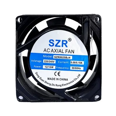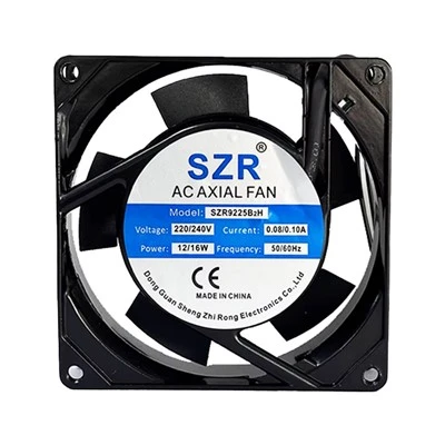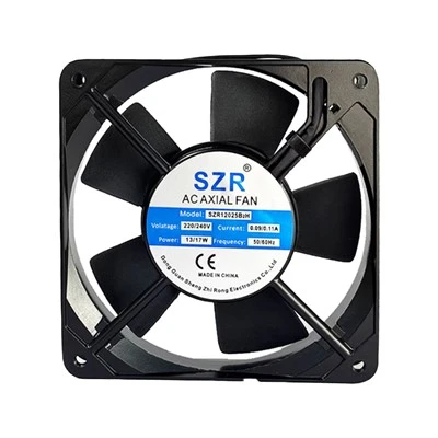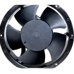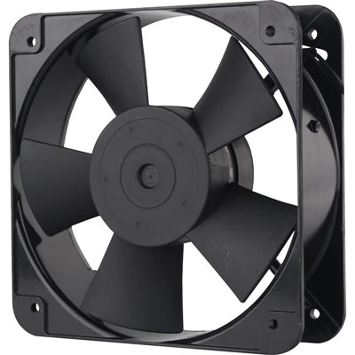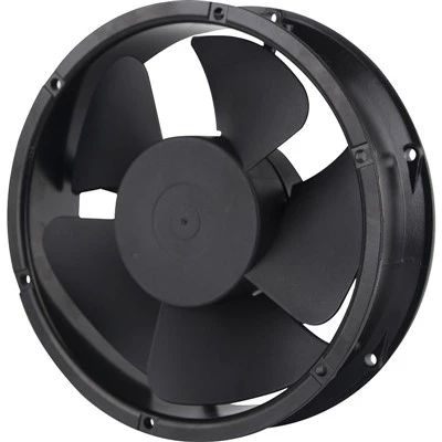
I. General Basic Knowledge for Cooling Fan Selection
The following essential information must be confirmed when selecting fans:
★ Fan dimension size
★ Confirm whether the fan is DC (Direct Current) or AC (Alternating Current) type
★ Rated supply voltage:
AC options: 220V, 110V, 380V; DC options: 5V, 12V, 24V, 36V, 48V
★ Bearing type: Ball Bearing or Sleeve Bearing
★ Air flow rate and rotational speed (e.g., cubic meters per minute, cubic feet per minute)
★ Static pressure value
Fan Selection Parameter Range
- Voltage: 3V ~ 220V
- Dimension: 20mm ~ 280mm
- Rotational speed: 2000 ~ 25000 RPM
- Minimum noise: 20 dBA
- Functional features: PWM speed regulation, FG speed signal detection, RD rotation loss alarm, AS auto-restart, reverse polarity protection
- Protection performance: Auto-recovery protection, under-voltage protection, over-voltage protection, IP68 waterproof, moisture-proof, anti-corrosion, salt spray resistance
- Material: PBT plastic (UL94V-0 flame retardant, RoHS 2.0 environmental compliant)
- Bearing categories: Ball Bearing, Hydraulic Bearing, Sleeve Bearing
II. Introduction to Bearing Types
Sleeve Bearing
In traditional brushless DC fan motor design, the fan rotor assembly and its central shaft pass through the sleeve bearing, which is pivotally fixed at the center of the motor stator. A proper clearance is maintained between rotor and stator, as well as between shaft core and bearing to avoid shaft jamming and locked rotation.
After power supply input, the stator generates induced magnetic flux between rotor and stator. Controlled by the drive circuit, this magnetic field drives fan rotation. The conventional fan motor structure only includes one fan rotor, one stator and one drive circuit; it rotates via magnetic induction with the shaft pivoted inside the sleeve bearing.
Advantages of Sleeve Bearing
A. Resistant to physical impact, fewer damages during transportation
B. Low cost, with a large price advantage over ball bearings
Disadvantages of Sleeve Bearing
A. Ambient dust is drawn into the motor core during fan operation, mixing with lubricant around the bearing to form sludge, which creates running noise or even completely locks the fan
B. The inner bore of the bearing wears easily, leading to shorter service life
C. Not suitable for portable products
D. Narrow clearance between bearing and shaft core results in poor motor startup performance
E. High-temperature gas generated by friction between shaft core and bearing is blocked by oil retainers and washers at both ends of the bearing, forming nitrides that clog the clearance and hinder smooth fan rotation
Ball Bearing
Ball bearings rely on rolling metal spheres with point contact, which enables easy startup. A spring is matched with the ball bearing to push against its outer metal ring, so the full weight of the fan rotor rests on the ball bearing with indirect spring support. This design fits portable products used at various tilt angles, though drops and heavy shocks must be prevented to avoid bearing damage, excessive noise and shortened service life.
Advantages of Ball Bearing
A. Point-contact rolling of metal spheres delivers easy startup
B. Applicable to portable products frequently operated at different placement angles (avoid random dropping or impact)
C. Longer service life compared with sleeve bearings
Disadvantages of Ball Bearing
A. Fragile bearing structure that cannot withstand heavy physical impact
B. Rolling metal spheres produce louder noise during motor operation
C. Higher unit cost, lacking cost competitiveness against sleeve bearings
D. Unstable supply and controllable quantity of ball bearings
E. Spring-based positioning design complicates assembly work
III. Fan Operating Principles
Operating Principle of DC Fans
Per Ampere's Right-Hand Rule, current passing through a conductor generates a surrounding magnetic field. If the conductor is placed inside another fixed magnetic field, attractive or repulsive forces will be produced to drive motion.
A pre-magnetized rubber magnet is attached inside the blades of a DC fan. Two sets of coils are wound around the silicon steel core at the axis, paired with a Hall effect sensor as a synchronous detection unit to control a switching circuit. This circuit alternates power supply to the two coil sets, generating alternating magnetic poles on the silicon steel core. The attraction and repulsion between these poles and the rubber magnet overcome the fan's static friction to spin the blades. The Hall sensor provides continuous synchronous signals to sustain rotation, and rotation direction follows Fleming's Right-Hand Rule.
Operating Principle of AC Fans
AC fans differ from DC fans: AC supply voltage alternates positive and negative polarity continuously, unlike fixed DC voltage. A dedicated control circuit is required to alternate coil energization and generate alternating magnetic fields.
The switching speed of magnetic poles on the silicon steel core is determined by the fixed frequency of AC mains. Higher frequency leads to faster magnetic field alternation and theoretically higher rotational speed, similar to how more pole pairs increase DC fan speed. However, excessively high frequency will cause poor startup performance.
IV. Noise Specifications
Fan noise is measured in an anechoic chamber with background noise below 15 dBA. The test fan runs in free air, with a sound level meter placed 1 meter away from the air intake.
Fan noise values are plotted as sound pressure level (SPL) across octave bands. The perceptual effect of dBA changes is shown below:
A. 3 dBA change: Barely perceptible
B. 5 dBA change: Clearly noticeable
C. 10 dBA change: Perceived as twice as loud
Noise Level Classification
A. 0 ~ 20 dBA: Extremely faint
B. 20 ~ 40 dBA: Faint
C. 40 ~ 60 dBA: Moderate
D. 60 ~ 80 dBA: Loud
E. 80 ~ 100 dBA: Very loud
F. 100 ~ 140 dBA: Deafening
V. Air Flow Rate & Unit Definitions
(Click: Air Flow & Static Pressure Automatic Conversion Table)
- CFS: Cubic Feet Per Second (ft³/s)
- CFM: Cubic Feet Per Minute (ft³/min)
- CMS: Cubic Meter Per Second (m³/s)
- CMM: Cubic Meter Per Minute (m³/min)
- CMH: Cubic Meter Per Hour (m³/h)
- L/s: Liter Per Second
- L/min: Liter Per Minute
VI. Static Pressure & Unit Definitions
Static Pressure Unit Explanations
- N (Newton): 1 N = 0.101097 kgf
- Pa (Pascal): 1 Pa = 1 N/m²
- mmAq (Aq = Aqua, meaning water column, also written mmH₂O): 1 mmAq = 1 kg/m²
- atm (Standard Atmospheric Pressure): 1 atm equals 760 mmHg under 0°C dry air. Mercury is 13.5947 times denser than water, so 1 atm is also equivalent to 10332 mmH₂O
- bar: 1 bar = 10⁵ Pa
Definition of Air Volume
Air volume (Air quantity / Capacity) refers to the volume of air drawn by a blower per unit time, denoted as Q (m³/min) for intake air. Gas volume changes with pressure and temperature; therefore, discharge air volume measurements must specify the ambient pressure and temperature, hence the term "intake air volume".
Standard Air Condition
Humid air at 20°C, 760 mmHg atmospheric pressure and 65% relative humidity; specific weight = 1.2 kg/m³
Reference Air Condition
Dry air at 0°C, 760 mmHg atmospheric pressure and 0% relative humidity; specific weight = 1.293 kg/m³, expressed as Nm³/min (normal cubic meters per minute)
VII. Ingress Protection (IP) Rating
IP ratings are a set of physical standards defined under IEC 60529 (BS EN 60529:1991). Each IP rating consists of two digits (e.g. IP55):
1. The first digit defines protection against human contact and solid particles
2. The second digit defines protection against liquid water ingress
Reference Motor Insulation Temperature Classes
The maximum allowable operating temperatures of insulation systems are standardized by the National Electrical Manufacturers Association (NEMA):
|
Temperature Tolerance Class |
Max Operating Temp |
Permissible Temp Rise (Motor Service Factor 1.0) |
Permissible Temp Rise (Motor Service Factor 1.15) |
|
A |
105°C / 221°F |
60°C |
70°C |
|
B |
130°C / 266°F |
80°C |
90°C |
|
F |
155°C / 311°F |
105°C |
115°C |
|
H |
180°C / 356°F |
125°C |
N/A |
Temperature conversion formula: T(°F) = T(°C) × 9/5 + 32
Permissible temperature rise is calculated against a 40°C baseline ambient temperature.
Total operating temperature = Baseline ambient temperature + Permissible temperature rise + Coil hot spot margin.
Example for Class F insulation: 40°C + 105°C + 10°C = 155°C
Motors should not run continuously at their maximum rated temperature. Service life is halved for every 10°C rise above the rated temperature.
Class B insulation is widely used for 60Hz North American motors; Class F insulation is standard for global 50Hz motors.